
With the rapid expansion of energy storage systems, managing thermal conditions and ventilation in battery housing facilities has become a key challenge in the design of energy infrastructure. Batteries generate considerable heat during charging and discharging cycles and are highly sensitive to their operating environment, requiring stable and well-controlled thermal conditions.
This project evaluates the thermal performance and airflow patterns within a battery house in Regensburg, Germany, using Computational Fluid Dynamics(CFD) simulation. The study focuses on analyzing temperature distribution, airflow behavior, and the potential formation of hot and cold spots under peak summer heat and winter cold conditions; providing critical insights for integrating technical performance with architectural design in energy-oriented projects.
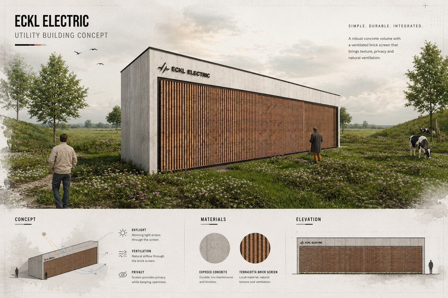
The battery house in Regensburg, Germany, as part of an energy storage infrastructure, contains multiple battery racks within an enclosed space. Due to the following factors:
this facility demands a precisely designed ventilation and cooling system.
The building, referred to as the Battery House Regensburg/Oberhub, was subjected to CFD analysis to evaluate its thermal behavior and airflow patterns under critical annual conditions. The results were subsequently used to optimize the ventilation system.
Inadequate performance in controlling thermal conditions can lead to the formation of hot spots, reduced efficiency, shortened equipment lifespan, and increased safety risks. Therefore, airflow management and temperature control in such spaces are of critical importance.
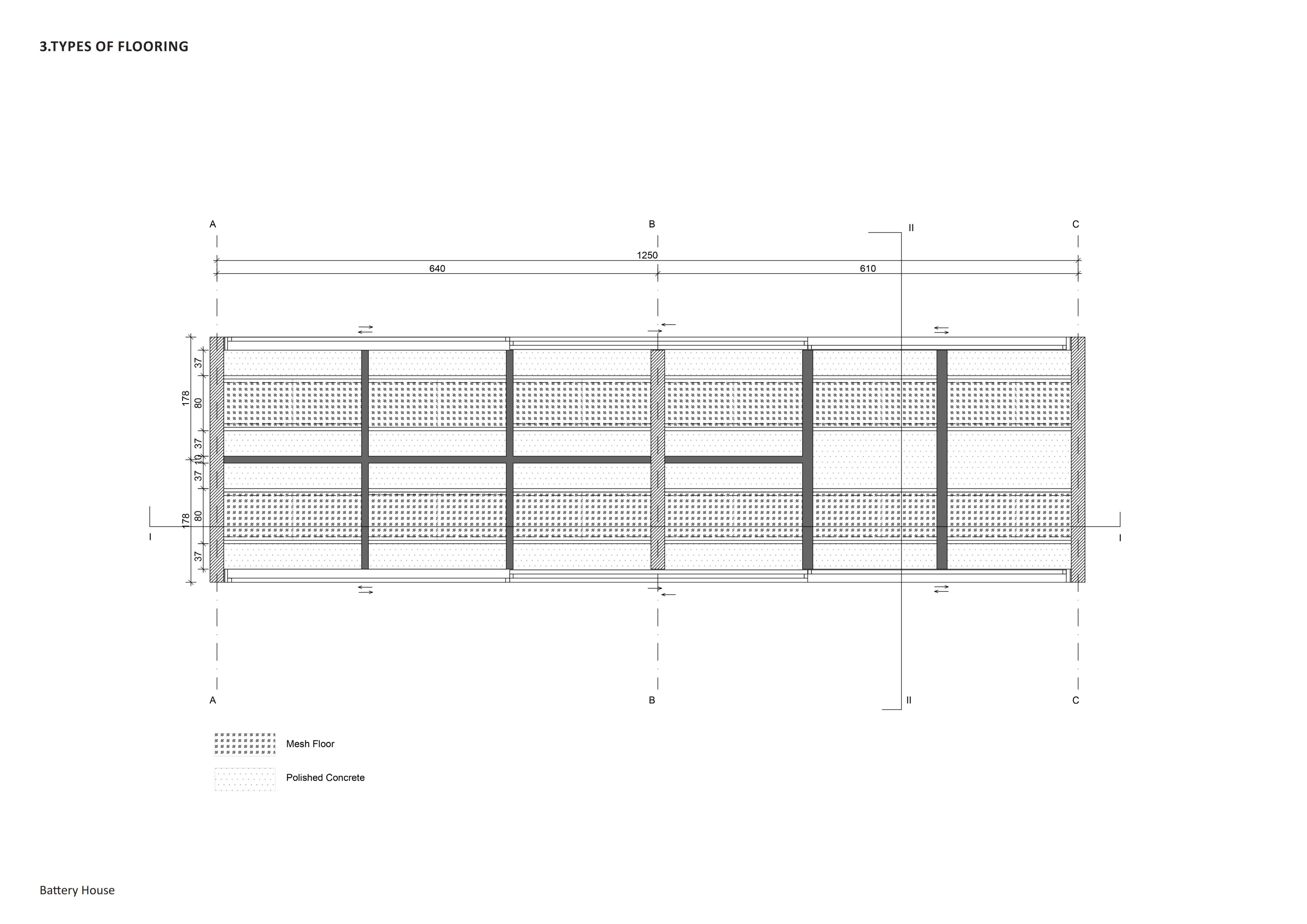
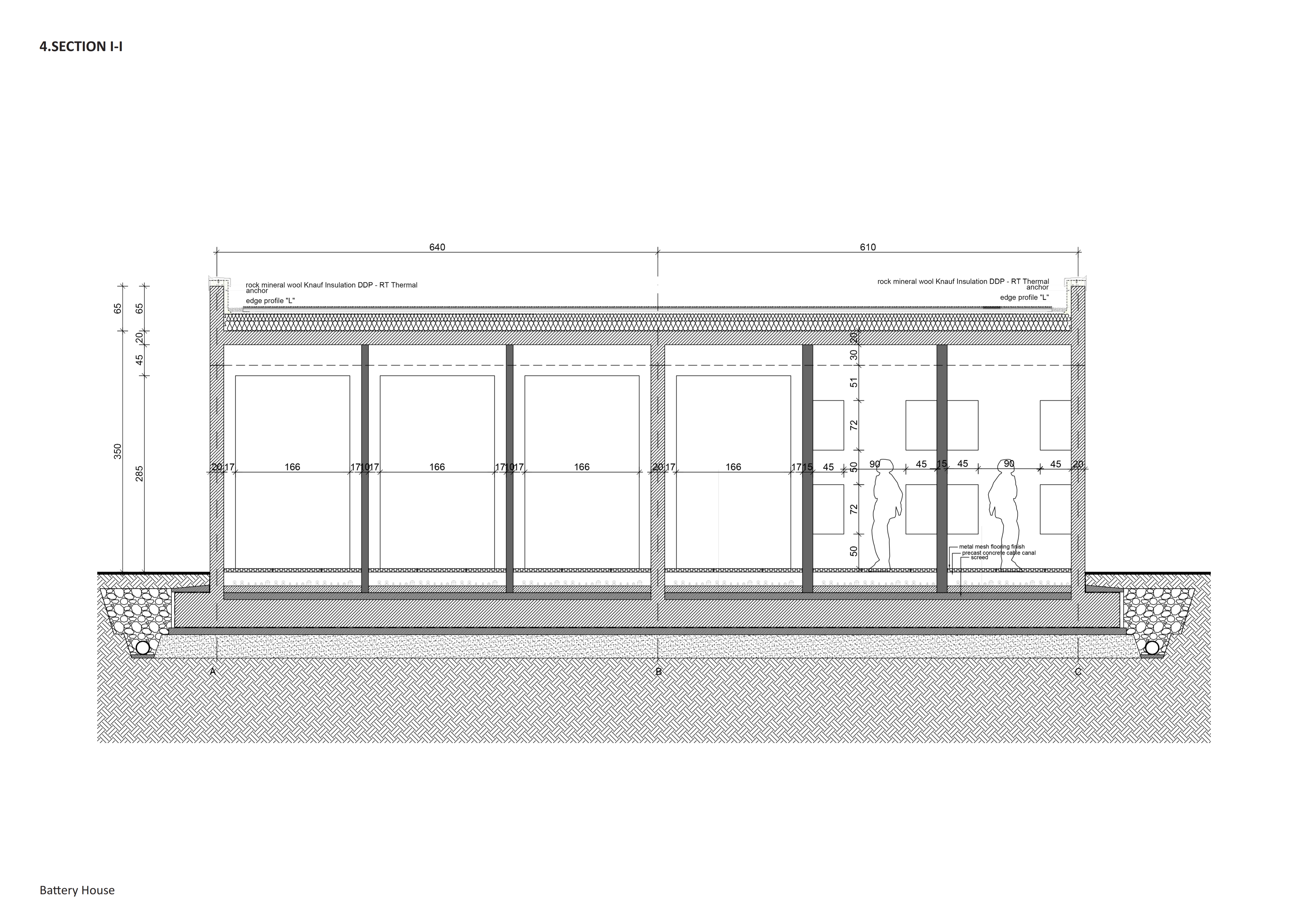
The thermal performance and ventilation of the battery house were evaluated using Computational Fluid Dynamics (CFD) simulation under peak winter cold and peak summer heat conditions.
The primary objectives were to assess temperature distribution and airflow patterns among the battery racks, ensuring that temperatures remain within equipment limits, maintaining thermal uniformity, and preventing the formation of hot spots.
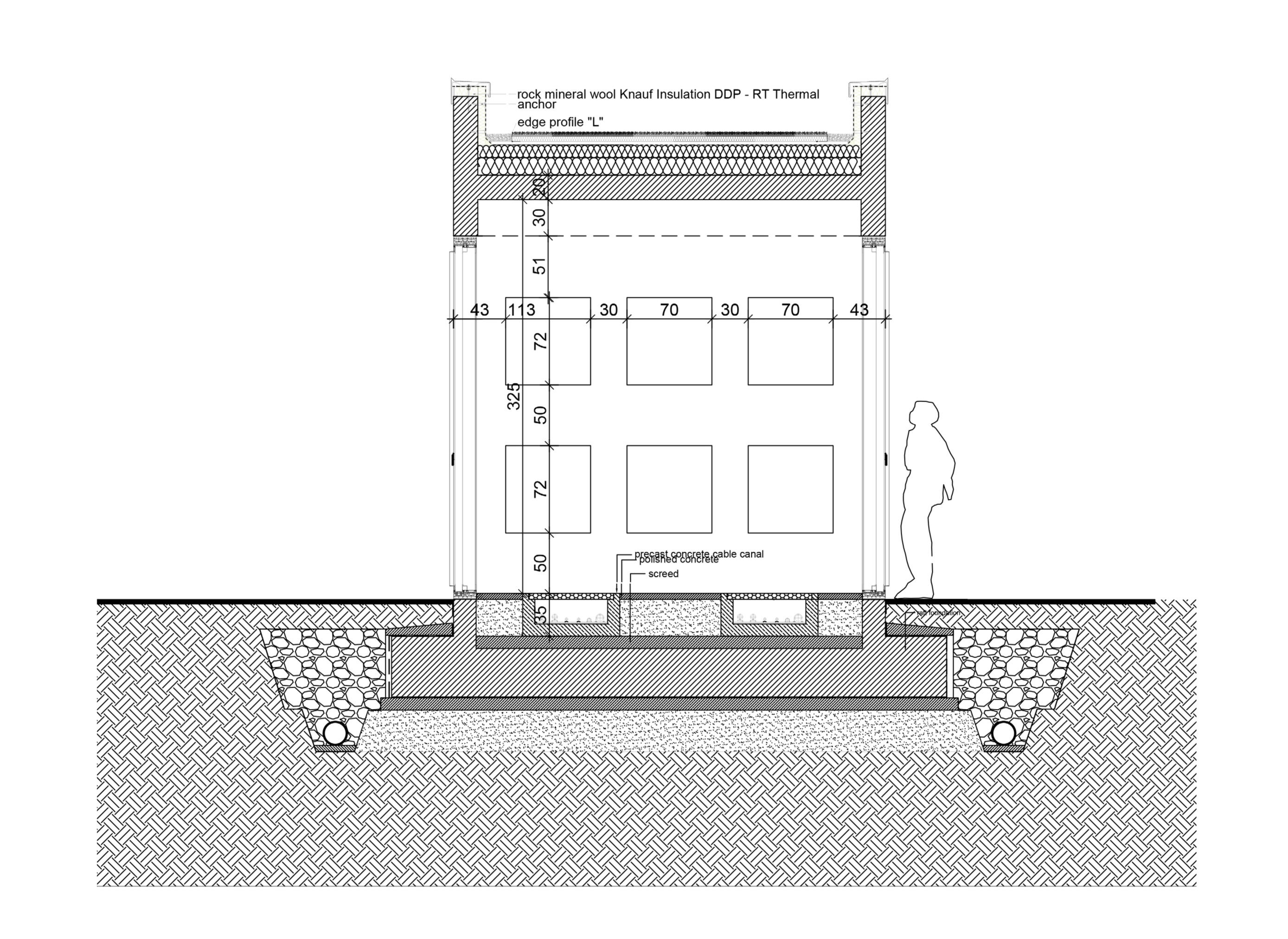
A three-dimensional model of the project was developed based on the actual arrangement of battery racks, the positioning of air inlets and outlets, and the heat generation rates of the equipment. The results obtained from the CFD analysis served as the basis for proposing strategies to optimize airflow paths, reduce temperature variations between racks, improve ventilation uniformity, and enhance both the safety and energy efficiency of the ventilation system.


In the summer analysis, the conditions were assumed as follows:
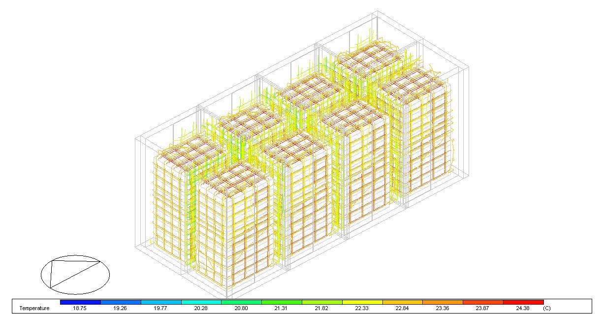
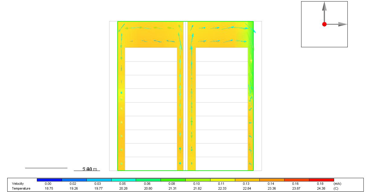
The simulations indicate a vertical temperature gradient, with higher temperatures observed near the upper levels of the racks and below the ceiling. Proper placement of exhaust openings in the upper region of the room is crucial to remove accumulated warm air and to avoid excessive temperatures at the top batteries.
Local hot spots tend to form in areas with reduced air velocity, such as behind the racks or in corners far from the main airflow paths. CFD visualization of temperature and velocity helps pinpoint these zones so that rack spacing, airflow direction, or local air supply can be improved.

When supply air is distributed along the aisles between racks and exhausts are positioned to create an effective flow path, the temperature difference between the warmest and coolest racks can be kept within acceptable limits. Otherwise, an increase in airflow rate, re‑positioning of diffusers, or the use of dedicated ducting may be required.
In winter, the ambient conditions are much colder and the main concern is over‑cooling and excessive temperature gradients within and between racks.
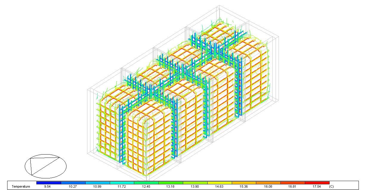
Despite the low supply air temperature, internal heat generation from the batteries usually keeps their surrounding air within the acceptable range. CFD is used to verify that, particularly near supply diffusers, no part of the racks falls below the minimum recommended temperature.
Direct impingement of very cold supply air on certain racks may create local cold spots and thermal stress on the cells. Adjusting diffuser orientation, using indirect air paths, or mixing zones can mitigate this risk.
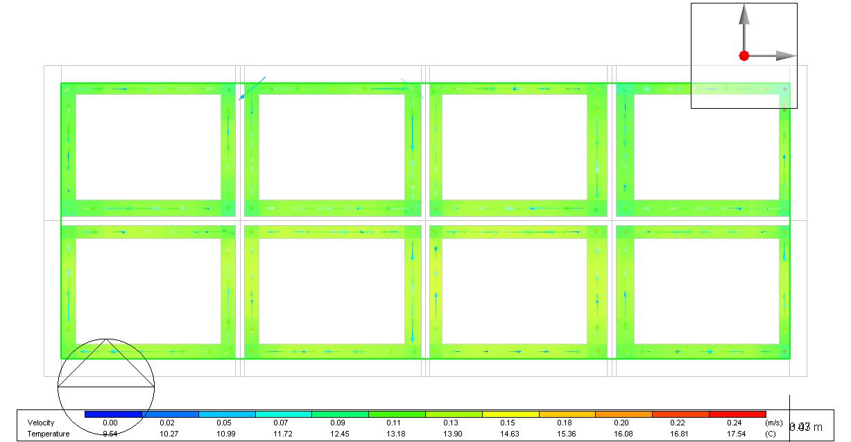
The winter simulations show that, in many scenarios, the waste heat from the batteries can significantly reduce the need for active heating. Intelligent control of fresh‑air volume and limited auxiliary heating may be sufficient, which improves overall energy efficiency.
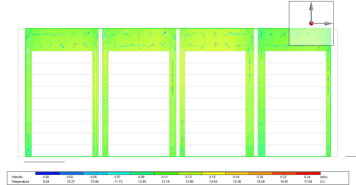
The combination of summer and winter analysis results demonstrates that proper design of airflow paths, the positioning of inlets and outlets, and the arrangement of racks can:
This CFD study, focused on optimizing the thermal performance and ventilation of the battery house in Regensburg/Oberhub, has provided a solid foundation for decision-making during the design, implementation, and operational optimization phases.
For consultation and energy management of your projects, please contact us.

در صورت داشتن هرگونه سوال، با ما در تماس باشید …

If you have any questions, feel free to contact us.
Adding {{itemName}} to cart
Added {{itemName}} to cart